
Achieving a flawless, mirror-like surface finish on a milling machine is a persistent challenge for machinists. Tool marks, scalloping, and surface cloudiness often ruin critical facing operations, leaving operators struggling to meet tight aesthetic and tolerance standards.
While standard indexable end mills and general-purpose cutters are the typical default choices for bulk material removal, they rarely deliver the pristine finishes required for high-end components. Stepping up to specialized facing tooling unlocks the ability to achieve superior flatness and surface geometry, directly reducing costly post-machining polishing.
However, optimizing this process requires balancing machine rigidity and power limits; for instance, while a multi-insert face mill excels on rigid CNCs, a single-point fly cutter is often the superior choice for achieving mirror finishes on low-horsepower manual mills cutting 6061 aluminum.
This article provides an in-depth comparison of fly cutters versus face mills, analyzing their mechanics, surface finish capabilities, and operational parameters to help you select the optimal tool for your next facing operation.
| Factor | Summary |
|---|---|
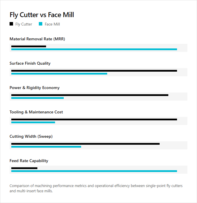
| Material Removal Rate (MRR) | Face mills utilize multiple indexable carbide inserts to achieve a significantly higher material removal rate, whereas fly cutters rely on a single-point tool and remove material much slower. |
| Surface Finish | Fly cutters typically produce a superior, mirror-like surface finish because the single cutting edge eliminates the minute tool-path height variations caused by multi-tooth mismatch on a face mill. |
| Power and Rigidity Requirements | Face mills require high spindle horsepower and substantial machine rigidity to engage multiple teeth simultaneously, while fly cutters exert low cutting forces making them suitable for light-duty hobbyist mills. |
| Tooling Cost and Maintenance | Fly cutters are highly economical because they use simple, easily resharpened high-speed steel (HSS) tool bits, whereas face mills incur higher operating costs due to the need for multiple indexable insert replacements. |
| Cutting Width (Sweep) | Fly cutters offer an adjustable bar design that allows machinists to customize a wide cutting diameter for large workpieces, while face mills have a fixed cutting diameter determined by the physical body of the cutter. |
| Feed Rate | Face mills can operate at much faster table feed rates because the chip load is distributed across multiple teeth, whereas fly cutters must be run at a slow feed rate to avoid overloading the single cutting edge. |
Minimizing Axial Runout: Face Mills vs. Fly Cutters
Achieving a flawless surface finish on a milling machine requires minimizing axial runout variation. In multi-insert face mills, minute manufacturing tolerances and seating variations among the multiple inserts introduce axial runout, leading to uneven tooth engagement and microscopic ridges. In contrast, single-point fly cutters eliminate this variation entirely. Because a fly cutter utilizes only one cutting edge, axial runout variation between teeth is non-existent during the sweep, producing an exceptionally uniform, mirror-like surface finish.
While face mills offer superior material removal rates by distributing the chip load, they demand precise setup and high-quality tooling to mitigate runout. Fly cutters sacrifice metal removal speed for surface quality, requiring less power and machine rigidity to perform wide facing passes. Single-point fly cutters are ideal for prototyping toolmakers seeking pristine finishes on lighter machinery, whereas multi-insert face mills are best suited for high-volume production machinists prioritizing throughput and rapid cycle times.
Optimizing Feed per Tooth for Cusp Height and Roughness
Achieving a target surface roughness (Ra) in milling requires precise control over the feed per tooth. A fly cutter, utilizing a single cutting edge, eliminates insert runout entirely. This simplifies the calculation of theoretical cusp height, which is governed solely by the feed rate and the tool's nose radius, consistently producing an exceptionally uniform, mirror-like surface finish.
In contrast, a face mill features multiple inserts to distribute the workload, enabling much higher table feed rates. Optimizing the feed per tooth on a face mill requires precise insert height alignment to prevent a single dominant tooth from dictating the cusp height and degrading the Ra value. Fly cutters are highly suited for prototype machinists and hobbyists seeking flawless finishes on low-horsepower setups, while face mills are best for high-volume industrial operators requiring rapid, high-efficiency material removal.
Maximizing Sweep Diameter for Ridge-Free, Single-Pass Milling
To achieve a seamless surface finish on a milling machine, maximizing the cutter's sweep diameter is essential. Both fly cutters and face mills allow for single-pass radial engagement, which spans the entire width of the workpiece. This technique completely eliminates the stepover ridges associated with multiple overlapping toolpaths, resulting in superior flatness.
While a face mill utilizes multiple inserts to distribute the chip load and enable rapid material removal, it requires significant spindle horsepower to run at large diameters. In contrast, a fly cutter uses a single tool bit to sweep a massive diameter with minimal power requirements, delivering an exceptional finish at a slower feed rate. Precision instrument makers seeking an ultra-smooth finish on light-duty manual machinery favor the fly cutter, whereas high-volume CNC machinists prioritizing throughput and structural rigidity require the face mill.
Mechanical Burnishing Using Face Mill Wiper Inserts
In precision milling, choosing between a fly cutter and an indexable face mill depends on specific production goals. While fly cutters deliver excellent surface finishes using a single cutting edge, face mills optimize metal removal rates. Machinists can elevate face mill performance by implementing a single wiper insert alongside standard roughing inserts. Positioned slightly lower than the other inserts, the wiper act as a burnishing tool, mechanically compressing surface microscopic peaks to achieve a mirror-like finish at high feed rates.
Integrating wiper technology delivers the surface quality of a fly cutter with the efficiency of multi-insert tooling. Fly cutters remain the preferred choice for hobbyists and prototype machinists prioritizing low-cost, flawless finishes on low-rigidity machines, while indexable face mills with wiper inserts are tailored for high-production manufacturing professionals who demand maximum throughput and superior surface integrity.
Balancing Speed and Feed to Manage Thermal Deformation
Managing thermal deformation on a workpiece surface requires a precise balance of Surface Feet per Minute (SFM) and feed rate. Face mills utilize multiple cutting inserts to distribute the thermal load, which permits higher SFM and rapid feed rates while preventing localized heat buildup. Conversely, fly cutters employ a single-point tool that concentrates thermal energy. To mitigate thermal deformation when using a fly cutter, machinists must reduce the SFM and carefully adjust the feed rate to ensure proper chip evacuation and heat dissipation.
Achieving the optimal surface finish without warping the material depends heavily on selecting the correct tool for the specific application. Face mills are ideal for high-volume industrial machinists requiring rapid material removal and consistent thermal management, while fly cutters are suited for toolmakers and hobbyists seeking ultra-flat, mirror-like finishes on low-horsepower machinery.
Controlling Chatter and Harmonics via Asymmetric Cutting Forces
Controlling spindle harmonics and tool chatter during surfacing requires strategic management of cutting force distribution. A fly cutter utilizes a single-point tool, creating an inherently asymmetric, interrupted cut. This single impact per revolution prevents the accumulation of resonant frequencies, effectively suppressing continuous chatter in less rigid setups. Conversely, multi-insert face mills risk inducing harmonic vibrations if the teeth contact the workpiece at perfectly symmetrical intervals.
To mitigate this resonance, advanced face mills employ unequal insert spacing, distributing cutting forces asymmetrically to disrupt harmonic feedback. While fly cutters offer exceptional surface flatness at lower material removal rates, face mills leverage multiple cutting edges for high-efficiency production. Prototyping machinists seeking pristine finishes on light-duty manual mills favor the fly cutter, whereas industrial manufacturing engineers requiring rapid cycle times and high-rigidity metal removal utilize asymmetric face mills.
Optimizing Lead Angles for Axial Cutting Forces
When choosing between a fly cutter and a face mill, managing cutting forces is essential for surface quality and tool longevity. Selecting the correct insert lead angle is key to this process; a larger lead angle, such as 45 degrees, redirects cutting forces axially up the spindle rather than radially into the workpiece. This axial redirection minimizes vibration and deflection, protecting thin-walled setups and maximizing stability on less rigid machines.
Face mills employ multiple inserts with optimized lead angles to distribute these axial forces for rapid material removal. Fly cutters use a single-point tool, which reduces power requirements but concentrates the cutting forces. High-volume industrial machinists requiring rapid, stable metal removal benefit most from face mills, whereas toolmakers and hobbyists seeking flawless surface finishes on light-duty equipment are better suited to fly cutters.
Leave a comment