Engineers and machine shop managers frequently struggle to fabricate highly complex geometries without bottlenecking production or incurring prohibitive cycle times. While standard equipment financing and traditional capital allocation allow facilities to secure baseline machinery, choosing the wrong spindle configuration can severely drain operational resources.
Optimizing your selection between three-axis and five-axis CNC milling machines grants your enterprise unprecedented manufacturing agility and a drastic reduction in part setups. This technological advantage remains highly effective, provided that your engineering team can navigate the steeper learning curve of multi-axis CAM programming.
For instance, the single-setup production of intricate aerospace impellers demonstrates how five-axis machining slashes labor costs while maintaining tight tolerances. In this guide, we will compare the structural configurations, cost-to-capability ratios, and specific geometric indicators that dictate when to utilize three-axis versus five-axis CNC milling machines.
| Factor | Summary |
|---|---|
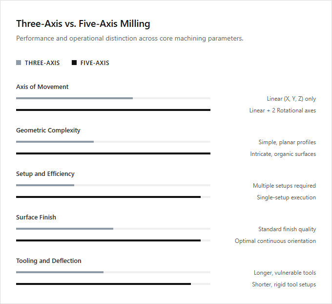
| Axis of Movement | Three-axis milling operates along the X, Y, and Z linear axes, whereas five-axis milling utilizes two additional rotational axes to maneuver the cutting tool. |
| Geometric Complexity | Three-axis machines are limited to simpler, planar geometries, while five-axis machines easily fabricate intricate, organic surfaces with complex undercut features. |
| Setup and Efficiency | Five-axis machining significantly reduces cycle times by enabling multi-sided machining of the workpiece in a single setup. |
| Surface Finish | Five-axis milling achieves superior surface roughness profiles by maintaining the optimal orientation of the end mill relative to the workpiece. |
| Tooling and Deflection | Five-axis milling allows the use of shorter cutting tools, which minimizes tool deflection and vibration during high-speed machining. |
Rotational Integration vs. Translational Axis Limitations
Three-axis milling machines operate strictly along the translational X, Y, and Z axes. While highly efficient for planar surfaces, this configuration limits the cutting tool to a single perpendicular orientation, which requires operators to manually reposition workpieces when machining complex, multi-sided components.
Five-axis milling overcomes these physical limitations by integrating rotational A and B axes alongside the standard translational paths. This integration allows the tool or workpiece to tilt and rotate continuously, enabling the fabrication of intricate contours and deep undercuts in a single, continuous setup.
Basic three-axis systems are ideal for general fabricators producing straightforward prismatic components, while advanced five-axis machinery is suited for high-precision aerospace and medical engineers who require complex, organic geometries.
Elimination of multiple setups and specialized fixturing via single-setup machining
Three-axis milling machines operate along the X, Y, and Z axes, which often requires repositioning the workpiece manually for complex geometries. This traditional approach necessitates multiple setups and specialized, costly fixturing to achieve various angles, increasing production time and the margin for human error.
Five-axis milling introduces two rotational axes, enabling the cutting tool to approach the workpiece from any direction. This capability facilitates single-setup machining, completely eliminating the need for complex fixtures and manual repositioning. Consolidating operations into a single cycle achieves superior geometric accuracy and reduced lead times.
Three-axis machines are ideal for general workshop technicians producing simpler, prismatic components, whereas five-axis systems are suited for advanced aerospace and medical manufacturing specialists requiring highly complex, tight-tolerance geometries.
Minimizing Tool Deflection via Shorter Overhang and Cutters
In three-axis milling, reaching deep cavities often requires long, slender cutters. This extended tool overhang increases the risk of tool deflection, which compromises surface finish and dimensional accuracy. Five-axis milling resolves this limitation by tilting the workpiece or the machining head. This angular flexibility allows the tool to approach the part at optimal angles, enabling the use of much shorter, more rigid cutters.
Shorter cutters significantly reduce tool deflection and vibration, leading to superior surface quality and extended tool life. This stabilization allows for higher feed rates and more aggressive cutting depths. Traditional three-axis machines are ideal for general machinists fabricating straightforward prismatic components, while five-axis systems are suited for high-precision aerospace and medical manufacturers producing complex, contoured geometries.
RTCP for Toolpath Optimization and Collision Avoidance
Three-axis milling operates along standard X, Y, and Z linear axes, which limits tool orientation and often requires complex fixtures to avoid interference. Five-axis milling introduces two rotational axes, allowing the spindle to maneuver around intricate geometries. To maximize five-axis efficiency, Rotational Tool Center Point (RTCP) technology dynamically adjusts these rotary axes, maintaining the tool tip's precise contact point relative to the workpiece surface.
This advanced capability optimizes toolpaths by keeping cutting speeds consistent and reducing cycle times. Real-time RTCP compensation also enhances collision avoidance, as the control system automatically recalculates spindle positions to prevent interference with the machine envelope. Standard three-axis setups suit general fabricators producing simple, flat parts, whereas five-axis systems equipped with RTCP are ideal for advanced aerospace and medical programmers managing highly complex geometries.
Multi-Axis Interpolation for Superior Surface Finish
In three-axis machining, tool movement is restricted to translational paths, requiring small stepover increments that inherently leave scallop heights on contoured surfaces. Minimizing these ridges to achieve a smooth finish requires extensive cycle times or manual post-processing. Conversely, five-axis milling utilizes continuous multi-axis interpolation to rotate the workpiece or spindle head dynamically. This maintains the cutter at an optimal contact angle relative to the part geometry, which drastically reduces scallop height and delivers a superior, mirror-like surface finish directly from the machine.
Eliminating secondary hand-finishing processes accelerates production cycles while maintaining tighter geometric tolerances. Standard three-axis systems are ideal for general job shops producing prismatic components, whereas five-axis technology is suited for high-precision aerospace and medical manufacturers requiring complex, organic geometries.
Accessing Complex Undercuts and Cavities Without Custom Tooling
Conventional three-axis milling operates along the X, Y, and Z axes, which limits tool access when encountering complex geometries. Machining deep cavities or intricate undercuts on these systems often requires specialized, custom-angled tooling and multiple setups. In contrast, five-axis milling introduces two rotational axes, allowing the spindle to approach the workpiece from any angle. This flexibility enables seamless access to deep recesses and complex negative drafts using standard, shorter cutting tools.
This multi-axis capability eliminates the need for custom fixtures, reducing setup times and improving surface finishes on contoured parts. Three-axis systems remain highly efficient for simpler, flat-faced components, whereas five-axis technology is essential for sophisticated aerospace and medical devices. Three-axis milling is ideal for general job-shop machinists producing standard prismatic components, while five-axis systems are suited for advanced manufacturing specialists producing highly complex, organic aerospace geometries.
5-Axis CAM Post-Processing and G-Code Generation
Three-axis milling operates on standard linear Cartesian coordinates, requiring relatively straightforward CAM programming and G-code generation. In contrast, five-axis simultaneous milling introduces two rotational axes, significantly escalating the complexity of toolpath calculations. Generating G-code for five-axis machines demands advanced CAM post-processors capable of managing machine-specific kinematic configurations, tool center point control, and real-time collision avoidance.
The post-processor must translate complex multi-axis trajectories into precise angular and linear coordinates, accounting for pivot length offsets and rotational limits. This intricate kinematic synchronization ensures smooth tool engagement and prevents tool-holder interference during complex surface machining. Standard three-axis systems are ideal for general machinists producing prismatic components, while simultaneous five-axis setups are suited for specialized aerospace and medical programmers manufacturing highly complex, organic geometries.
Leave a comment