Designing an efficient pneumatic conveying system often leaves plant engineers grappling with a costly frustration: selecting a regenerative blower that maintains material velocity without causing line blockages or skyrocketing energy bills. While relying on standard manufacturer datasheets and generic sizing software is the traditional starting point, these standard baselines rarely account for real-world system friction.
Achieving the precise equilibrium between open-flow rate and maximum static pressure is critical, as mastering this curve grants your operation seamless material transfer and drastically reduced downtime. As a stipulation, however, operators must recognize that these pneumatic dynamics are highly sensitive to line routing and piping bends.
For example, conveying heavy plastic pellets requires a high-pressure threshold to overcome inertia, whereas moving fine flour demands sustained volume flow. In this guide, we will demystify the trade-offs between open-flow rate and static pressure, explore how to calculate your system's true operating point, and outline a reliable framework for selecting the optimal blower.
| Factor | Summary |
|---|---|
| Impeller Blade Geometry | The specific configuration of the impeller blades determines the kinetic energy transfer, establishing the baseline ratio between maximum volumetric flow rate and shut-off head pressure. |
| System Resistance | The total friction loss within the connected ductwork forces the blower to operate at a specific intersection point on its characteristic performance curve. |
| Aerodynamic Slip | At high static pressures, air recirculates internally across the impeller tips, which significantly reduces the overall volumetric efficiency of the blower. |
| Rotational Speed | Applying the affinity laws, an increase in motor RPM proportionally elevates both the open-flow rate and the maximum pressure differential. |
| Air Density | Changes in ambient temperature and altitude alter fluid density, directly affecting the mass flow rate and the maximum achievable static pressure. |
| Deadhead Operation | Operating at maximum static pressure results in zero airflow, leading to rapid heat dissipation challenges due to compressed air recirculation within the housing. |
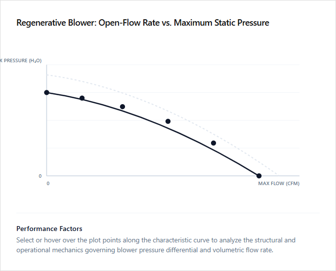
Operating point determination along the blower H-Q performance curve
Regenerative blowers operate along a performance curve defining the relationship between Open-Flow Rate (maximum volume at zero pressure) and Maximum Static Pressure (maximum resistance at zero flow). Determining the specific operating point requires intersecting this blower H-Q curve with the system's unique resistance curve. Piping diameter, system length, and media density dictate the backpressure, which shifts the actual operating point along the performance profile.
Selecting the correct operating point ensures optimum energy efficiency and prevents motor overload. High-flow, low-pressure configurations suit surface aeration, whereas low-flow, high-pressure setups excel in deep-water sparging. Engineers designing high-volume surface ventilation require the open-flow optimized models, while technicians managing deep-well extraction or high-resistance pneumatic conveying are best suited for the high-static pressure configurations.
Minimum Airflow for Dilute Phase Saltation Velocity
In dilute phase pneumatic conveying, selecting a regenerative blower requires a precise balance between open-flow rate and maximum static pressure. The system must consistently maintain a volumetric airflow rate that exceeds the minimum saltation velocity to prevent material from settling out of the air stream and obstructing the pipeline. As system resistance increases, the blower's operating point shifts along its performance curve, which reduces the actual volumetric airflow below the nominal open-flow rating.
To ensure reliable particle suspension, design engineers calculate the system pressure drop at the required saltation velocity and match it to a blower curve that guarantees sufficient flow under load. High open-flow configurations are ideal for plant operators conveying lightweight materials over short distances, whereas high static pressure models are suitable for system engineers managing dense particulates through complex, high-friction piping networks.
Overcoming total system pressure drop and equivalent length line losses
Regenerative blowers operate on an inverse relationship between open-flow rate and maximum static pressure. Selecting the appropriate blower requires a precise calculation of the total system pressure drop, which is heavily influenced by friction and equivalent length line losses from fittings, bends, and pipe diameter restrictions. As airflow encounters resistance within the piping network, system pressure rises, causing the actual operating flow rate to decrease from the maximum open-flow potential.
To ensure optimal performance, the blower must generate enough static pressure to overcome these cumulative line losses while maintaining the target volumetric flow. Engineers designing high-volume, low-resistance ventilation systems utilize high open-flow models, whereas facility technicians managing deep-tank aeration or dense-phase pneumatic conveying systems require high-pressure configurations.
High-Pressure Internal Slip Degrades Volumetric Efficiency
Regenerative blowers operate on a dynamic principle where air is continuously accelerated within a toroidal chamber. The operational performance of these units is defined by the inverse relationship between the open-flow rate, achieved at zero system resistance, and the maximum static pressure, reached at complete blockage. As system resistance increases, the pressure differential across the impeller blades rises, forcing a portion of the compressed air to recirculate across internal clearances. This phenomenon, known as internal slip, bypasses the seals from the high-pressure discharge back to the low-pressure suction zone.
This internal slip causes a severe degradation in volumetric efficiency, leading to a rapid decline in actual delivered airflow at elevated static pressures. Understanding this efficiency loss is critical to preventing motor strain and ensuring stable system performance. High-flow, low-pressure configurations are best suited for environmental technicians managing wastewater aeration, while high-pressure, low-flow models are ideal for industrial system designers managing pneumatic conveying or heavy-duty vacuum hold-down applications.
Optimizing the solids loading ratio to prevent line plugging
Regenerative blowers operate along a performance curve defined by the inverse relationship between open-flow rate and maximum static pressure. In pneumatic conveying, selecting the correct operating point on this curve is critical for optimizing the solids loading ratio. If the solids loading is too high for the available static pressure, system velocity drops below the saltation threshold, leading to material accumulation and line plugging.
To prevent these costly blockages, designers must balance high volumetric flow with sufficient static pressure to sustain continuous material suspension. High-flow, lower-pressure configurations are ideal for facility operators moving low-density, free-flowing materials over short distances, whereas high-pressure, lower-flow systems suit process engineers managing dense, abrasive particulates through complex routing networks.
Motor Sizing and BHP Curve Limits
Regenerative blowers operate on a performance curve where airflow decreases as static pressure increases. Unlike typical centrifugal fans, a regenerative blower experiences its highest brake horsepower (BHP) demand at the point of maximum static pressure, near shut-off conditions. Motor sizing must account for this peak demand to prevent thermal overload and system failure during periods of high system resistance.
To ensure reliable performance across the entire operational curve, engineers typically size motors to handle the maximum power draw at peak pressure rather than at open-flow. Systems can also utilize relief valves to artificially limit pressure, allowing for smaller, more economical motor selections. High-flow configurations are ideal for wastewater treatment operators requiring continuous aeration, while high-pressure systems are best suited for industrial vacuum specialists and pneumatic conveying technicians who manage high-resistance material transport.
ACFM Density Correction for Altitude and Temperature
Regenerative blowers operate along a performance curve defined by two extremes: the maximum open-flow rate, where air moves freely with zero resistance, and the maximum static pressure, representing the limit of the blower's capability against complete restriction. Environmental variables such as high altitude and elevated ambient temperatures significantly decrease air density. Industrial designers must apply specific density correction factors to convert Standard Cubic Feet per Minute (SCFM) to Actual Cubic Feet per Minute (ACFM), ensuring the blower delivers the necessary mass flow under local atmospheric conditions.
A reduction in air density lowers the pressure-generating capability of the system, meaning a blower operating at high elevations yields less physical pressure than its sea-level rating. High-volume open-flow configurations are suitable for facility managers requiring rapid, low-pressure material conveying, while high-pressure, density-corrected setups are ideal for process engineers managing deep-tank aeration systems in high-altitude regions.
Leave a comment